
An Interest In:
Web News this Week
- April 29, 2024
- April 28, 2024
- April 27, 2024
- April 26, 2024
- April 25, 2024
- April 24, 2024
- April 23, 2024
Some of Our Sources
- BoingBoing
- Mashable
- Joshua Blankenship
- The Logo Smith
- Smashing Magazine
- Creative Curio
- Reencoded
- Specky Boy
- Freelance Switch
- Dev To
Help Webnuz
Referal links:
How to Create a Retro 3D Displaced Text Effect in Adobe Photoshop

Combining 2D and 3D styles in different creative ways has been a part of multiple design trends over the years. This tutorial will show you how to use Photoshop's 3D tools and settings to create an abstract 3D displaced text effect, with a touch of a Retro/Memphis Style feel. Let's get started!
This text effect was inspired by the many Layer Styles available on GraphicRiver.
Tutorial Assets
The following assets were used during the production of this tutorial:
- Bahn Profont
- by Supertuts007 (Load the CHROMES.grd file)
1. How to Create the Background and 3D Elements Layers
Step 1
Create a new 1000 x 1000 px document, click the Create new fill or adjustment layer icon at the bottom of the Layers panel, and choose Gradient.
Create the gradient fill using the Colors #d99c9c to the left, #b294c5 in the center, and #72a9be to the right, and change the Angle to -120.

Step 2
Create the text in All Caps, each word in a separate layer, using the font Bahn Pro. Set the Size to 200 and the Tracking value to 100.

Step 3
Create three new layers, fill them with any color you like, and name them from bottom to top: Sphere, Pyramid, and Cylinder.

2. How to Create 3D Layers
Step 1
For each text layer you have, select it and go to 3D > New 3D Extrusion from Selected Layer.
Then, select the Sphere layer and go to 3D > New Mesh from Layer > Mesh Preset > Sphere, select the Pyramid layer and go to 3D > New Mesh from Layer > Mesh Preset > Pyramid, and select the Cylinder layer and go to 3D > New Mesh from Layer > Mesh Preset > Cylinder.

Step 2
Select all the 3D layers, go to 3D > Merge 3D Layers, and rename the merged layer3D Scene.

Step 3
To access the 3D mesh settings and properties, you’ll need to open two panels: the 3D panel and the Properties panel (both found under the Window menu).
The 3D panel has all the components of the 3D scene, and when you click the name of any of those, you’ll be able to access its settings in the Properties panel. So make sure to always select the tab of the element you want to modify in the 3D panel before you change its settings in the Properties panel.

Step 4
If you select the Move Tool, you’ll find a set of 3D Modes for it to the right of the Options bar. When you choose one of those, you can then click and drag to perform changes (on the selected element in the 3D panel).
Use those modes to change the Current View into an angle you like.

Step 5
Click the eye icon next to the Sphere, Pyramid, and Cylinder tabs to hide them.

3. How to Adjust the 3D Mesh Settings
Step 1
Select all the text mesh tabs in the 3D panel, and change their Extrusion Depth in the Properties panel to 0.

Step 2
Select each text mesh tab separately, click the 3D panel menu icon, and choose Move Object to Ground Plane.

Step 3
What we're going to do next is assign values to theZ Positionof each of the text meshes to set them apart from each other evenly.
So, for example, if you have three text meshes, you can change the one in the middle'sZ Positionto0, the one in the front's to300, and the one in the back's to-300.
To assign theZ Positionvalues, click the text mesh tab, and click the Coordinates icon at the top of the Properties panel to make the changes.

Step 4
You can use any values you think look best for your text and number of meshes, but just make sure to keep an equal distance between them.

4. How to Transform 3D Meshes
Step 1
Show the Sphere mesh and select its tab, pick the Move Tool, and use the 3D Axis to scale it up or down.
The arrows at the ends of the axis move the mesh, the part below them is used for rotation, and the cubes are used for scaling. The cube in the center is used to scale the object uniformly. All you need to do is click and drag the part you want to use.

Step 2
You can also use the Coordinates values for that, and if you click the Scale icon, you can check or uncheck the Uniform Scaling option depending on the result you want.

Step 3
Move the Sphere to the Ground Plane, and use the 3D Axis to move it to the final position.

Step 4
Repeat the same steps for the Pyramid and Cylinder meshes.
Notice how when scaling the Cylinder you might need to uncheck the Uniform Scaling box if you're using the Coordinates values.
Make sure to always move the objects to the Ground Plane once you're done transforming them.

5. How to Create Basic 3D Materials
Step 1
Select all the text Material tabs, and use these settings in the Properties panel (the color values used are in RGB):
- Diffuse: 255, 255, 255
- Specular: 183, 183, 183
- Shine: 20%

Step 2
Select the Sphere_Material tab, click the Diffuse icon in the Properties panel, and choose Remove Texture.

Step 3
Keep in mind that you can use any other values for the material settings, but the ones used here are:
- Diffuse: 163, 216, 236
- Specular: 121, 114, 114
- Shine: 30%
- Reflection: 3%
- Roughness: 30%

Step 4
Select all the Pyramid Material tabs, remove the Diffuse texture, and use these settings:
- Diffuse: 241, 155, 93
- Specular: 221, 199, 147
- Shine: 30%
- Reflection: 3%
- Roughness: 30%

Step 5
Select the Cylinder's Top_Material and Bottom_Material tabs, remove the Diffuse texture, and use these settings:
- Diffuse: 17, 17, 17
- Specular: 75, 72, 75
- Shine: 50%
- Reflection: 10%
- Roughness: 30%

Step 6
Select the Cylinder_Material tab, remove the Diffuse texture, and use these settings:
- Diffuse: 141, 128, 179
- Specular: 190, 194, 220
- Shine: 80%
- Reflection: 30%
- Roughness: 30%

6. How to Create a Simple Vertical Stripes Pattern
Step 1
Create a new 50 x 10px White filled document, use the Rectangular Marquee Tool to select the left half, and fill it with Black.

Step 2
Press Command-D to deselect, go to Edit > Define Pattern, type Stripes Pattern in the Name field, and click OK.

7. How to Create a Bump Texture
Step 1
Select the Cylinder_Material tab, click its Bump icon in the Properties panel, and choose New Texture.

Step 2
Set both the Width and Height values to 500 and click OK.

Step 3
This will open the new file; if not, select the Bump texture icon and choose Edit Texture.
Create a new layer and fill it with White.

Step 4
Double-click the new layer to apply a Pattern Overlay effect using the Stripes Pattern.

Step 5
Save and close the file.

8. How to Edit the UV Properties
Step 1
Click the Bump texture icon and choose Edit UV Properties.

Step 2
Change the Tile's V/Y value to 1and the U/X value to whatever looks best on your Cylinder mesh, and click OK.

9. How to Add a Mesh Environment Texture
Step 1
With the Cylinder_Material tab still selected, click the Environment folder icon at the bottom of the Properties panel, and choose New Texture.

Step 2
Change both the Width and Height values to 1000 and click OK.

Step 3
Duplicate the Background layer, and double-click the copy to apply a Gradient Overlay effect using the Stainless Steel 166c gradient fill.

Step 4
Save and close the file when you're done.

Step 5
You can try other gradient fills as well to get different lighting results.

10. How to Adjust Miscellaneous 3D Settings
Step 1
Select all text mesh tabs, and uncheck the Cast Shadows box in the Properties panel.

Step 2
Select the Scene tab, and under the Remove Hidden option in the Properties panel, check the Backfaces option.

Step 3
Click the Current View tab, and click the Orthographic icon in the Properties panel.
What this does is maintain parallel lines without convergence, which means displaying the meshes in accurate scale view without any perspective distortion.

Step 4
Now is a good time to choose a final camera angle, so that you can make any final changes to the scene.

Step 5
After you choose the final view, you can use the 3D Axis to move the meshes around, or scale them as needed.

11. How to Adjust a 3D Scene's Lighting
Step 1
Select the Infinite Light 1 tab, and change its Intensity to 20% and its Shadow Softness to 50%.

Step 2
Move the light to an angle that best suits your final view, and you can use the Coordinates values if needed to do so.

Step 3
Select the Environment tab, click the IBL texture icon, and choose Edit Texture.

Step 4
Add a Solid Color fill layer, and use the Color fill (100, 100, 100). Save and close the file when done.

Step 5
Go to 3D > Render 3D Layer. The rendering might take a while, but you can stop it any time by pressing the Esc key.

Step 6
Once the rendering is done, right-click the 3D Scene layer and choose Convert to Smart Object to avoid making any accidental changes.

12. How to Create a Basic Paper Shape
Step 1
Use the Rectangle Tool to create a rectangle shape behind the 3D Scene.

Step 2
Pick the Direct Selection Tool, and use it to select and move the anchor points, to get a parallelogram-like shape.
Use the 3D Scene as a reference to make the shape look like a part of it.

Step 3
Use the Add Anchor Point Tool to add an anchor point on each of the two vertical sides.

Step 4
Use the Direct Selection Tool to nudge each of the added points to make the vertical sides a little bit curved in the same direction.

Step 5
Add two more points, one on each of the sides next to the top right corner's anchor point. These will be used to create the corner fold, so keep that in mind when placing them.

13. How to Work With Anchor Points
Step 1
Rename the shape layer you have to Back, duplicate it, rename the copy to Front, and change its Fill Color to #ea6b9b.

Step 2
Select the Front layer, and use the Direct Selection Tool to click-drag the top right corner's anchor point inwards to the center, creating a basic folded shape.
You can then adjust the shape by moving the surrounding anchor points and their handles.
Any adjustments should be very minimum and subtle, and should not affect the part of the shape that's outside the two points around the corner.

Step 3
Pick the Delete Anchor Point Tool, select the Back layer, and click the top right corner's anchor point to delete it.
This will create the outer curve of the fold, which you can subtly adjust if necessary as well.

Step 4
Change the Back layer's Fill Color to #8b8b8b, and duplicate each of the Back and Front layers.

14. How to Create a Folded Shape
Step 1
Select both copy layers and move them on top of the 3D Scene layer.

Step 2
With both copy layers still selected, go to Layer > Combine Shapes > Subtract Front Shape. Rename the resulting layer to Fold, and change its Fill Color to #ee90b3.

Step 3
Pick the Direct Selection Tool, click the Path operations icon in the Options bar, and choose Merge Shape Components.

15. How to Add Gradient Overlays
Step 1
Double-click the Fold layer to apply a Gradient Overlay with these settings:
- Check the Dither box
- Blend Mode: Soft Light
- Opacity: 35%
- Angle: -157
- Use the Black, White gradient fill

Step 2
While the Layer Style box is still open, you can click-drag the gradient inside the shape to adjust its Angle if you like.

Step 3
When you're done, right-click the Fold layer, choose Copy Layer Style, right-click the Front layer, and choose Paste Layer Style.

16. How to Add Shadows
Step 1
Select the Back layer, and use the Direct Selection Tool to drag the bottom anchor points of the shape and create a shadow shape, which should follow the 3D Scene's shadow direction.

Step 2
Right-click the Back layer, choose Convert to Smart Object, and change its layer's Blend Mode to Multiply and its Opacity to 50%.

Step 3
Go to Filter > Blur > Gaussian Blur, and set the Radius to a value around 20.

Step 4
Command-click the Front layer's thumbnail to create a selection.

Step 5
Create a new layer below the Fold layer, name it Shadow, change its Opacity to 35%, and pick the Brush Tool.
Set the Foreground Color to Black, and use a soft round tip to add some shadow underneath the fold.
You can change the brush tip'sOpacity value in the Options bar to get subtler results.

17. How to Create Zigzag Lines
Step 1
Create a new layer on top of all layers, name it Lines, and pick the Pen Tool.
Choose the Path option in the Options bar, and click once to add anchor points that create zigzag shapes around the text.
When you're done creating a path, Command-click outside it to separate it from the next one.

Step 2
Pick the Brush Tool, choose a hard round 4 px tip, and hit the Return key to stroke the paths you have.
Pick the Direct Selection Tool and hit the Return key again to get rid of the work path.

Step 3
Double-click the Lines layer to apply a Gradient Overlay effect with these settings:
- Check the Dither box
- Angle: 157
- Create the Gradient using the Colors
#f5cd2cto the left and#f1e48bto the right.

18. How to Apply Global Adjustments
Step 1
Create a new layer on top of all layers, name it High Pass, and press the Command-Option-Shift-E keys to create a stamp.
Convert the layer into a Smart Object, and change its Blend Mode to Soft Light.

Step 2
Go to Filter > Other > High Pass, and change the Radius to 1.5.

Step 3
Add a Vibrance adjustment layer on top of all layers, and change the Vibrance value to 10.

Step 4
Add a Curves adjustment layer on top of all layers, and click-drag the center of the curve a little bit upwards to brighten up the image.

Step 5
Double-click the Curves layer to get its Blending Options.
We will use the Blend If's Underlying Layer's sliders to control how the Curves effect is applied.
So Option-click the Shadows slider to split it, and drag each of its ends to the right to exclude or protect the shadows from being affected by the Curves layer.
Splitting the slider will help create a gradual effect instead of a harsh one. So the right side will determine the amount of shadows protected, and the left side will fade the effect.
After adjusting the slider, change the Blend Mode to Soft Light, and the Opacity to 30%.

Step 6
Add another Curves adjustment layer, but this time, drag the curve's center downwards to darken the image.

Step 7
Double-click the second Curves layer to repeat the same steps, only this time you'll be excluding the Highlights, which means you'll be adjusting the Highlights slider.
So make sure to split it and drag its sides until you get a result you like, and change the Blend Mode and Opacity values when done.

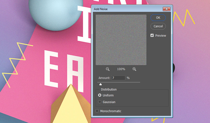
19. How to Add Noise
Step 1
Create a new layer on top of all layers, and name it Noise.

Step 2
Go to Edit > Fill, and change the Contents to 50% Gray.

Step 3
Convert the Noise layer into a Smart Object, and change its Blend Mode to Soft Light.

Step 4
Go to Filter > Noise > Add Noise, and change the Amount to 7 and the Distribution to Uniform.
You can use any other values you prefer as well.
Awesome Work, You're Done!
In this tutorial, we created a couple of text and shape layers, and converted them to 3D meshes. Then, we adjusted the meshes' settings and created their materials, as well as adjusting the scene's lighting to render it. After that, we used shape tools and options to create a folded paper shape and some zigzag lines. Finally, we added global adjustments to finish off the effect.
Please feel free to leave your comments, suggestions, and outcomes below.

Original Link:
TutsPlus - Design
More About this Source Visit TutsPlus - Design