
An Interest In:
Web News this Week
- April 16, 2024
- April 15, 2024
- April 14, 2024
- April 13, 2024
- April 12, 2024
- April 11, 2024
- April 10, 2024
Some of Our Sources
- Simplebits
- The Logo Smith
- Smashing Magazine
- Noupe
- Crazy Leaf Design
- CSS Tricks
- Spyre Studios
- Freelance Switch
- The Verge
- TechPowerUp
Help Webnuz
Referal links:
Create useful noise patterns with Academy award winning Ken Perlin
Randomness is weird. Apart from the fact that true randomness on computers can only be achieved with either really complex devices or fish tanks, it just doesn't look appealing, either.
Consider this piece of code:
<canvas id="c" width="640" height="360" /><script>const canvas = document.querySelector('#c')const paintGreyPixel = (canvas, x, y, grayScale) => { const context = canvas.getContext('2d') context.fillStyle = `rgba(0, 0, 0, ${grayScale})` context.fillRect(x, y, 1, 1)}for (let x = 0; x < 640; x++) { for (let y = 0; y < 360; y++) { paintGreyPixel(canvas, x, y, Math.random()) }}</script>What it does, is to paint every single pixel in a random grey scale. Math.random() combined with rgba and a black color results in a random shade of grey. And that's the result:

Meh.
Now imagine you want to do something with a randomly generated pattern like this. For example, using it as a height map for a game you're developing, or a simulate a wave pattern. Pretty useless for that, isn't it? You would want something that generates gradients instead.
Luckily, there are random noise algorithms that generate something useful. Ken Perlin has developed an algorithm that is aptly termed the Perlin noise generation. Perlin has actually received an Academy award for that. Yes, the movie trophy. The algorithm was originally developed for the movie Tron.
It generates something like this:

Much better, isn't it? And that noise could actually be used for height maps, water simulation and whatnot. Now, how do we generate that noise, though?
How the algorithm works
Let's have a deeper look at how the thing works that got Ken Perlin their golden statue. The Perlin noise algorithm works by dividing the plane into a grid of squares. The above example is 640 wide and 360 tall and was divided into a 60 by 60 grid. So, we have roughly 10.7 grid cells of width and 6 grid cells of height.

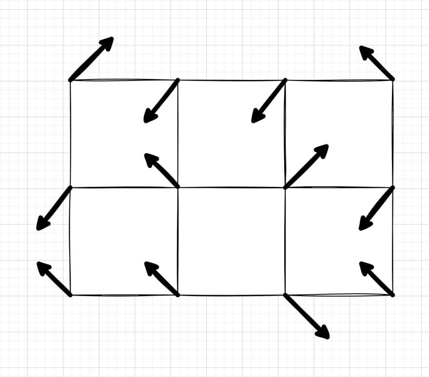
We then assign a vector to each grid intersection point. These vectors are usually chosen by random and out of a set of four, pointing to top-left, top-right, bottom-left and bottom-right. For smoother results, we can also generate these entirely random. We only need to make sure their length is uniform
These gradient vectors never change. Whenever we color a pixel, we use the four vectors of that grid cell to calculate the color. This keeps the number of random numbers to a minimum and uses what computers are actually good at: Calculations.
Now, to figure out what color a single pixel has, we first determine its grid cell and then the four gradient vectors of that grid cell, as well as the pixel's relative position within that grid cell as numbers between 0 and 1. We then calculate the vectors pointing from the edges of that grid cell to the pixel.

We now have 8 vectors, two per grid cell corner. We now calculate the dot products of the two vectors per grid corner to determine a single number per grid corner.
The dot product of the gradient vectors and the vectors pointing the edges, gives us four numbers. Essentially, the dot product tells us "what amount of one vector goes in the direction of another".
We can then "fade" the relative coordinates of the pixel within the grid cell to get smooth values. Perlin has defined a function for that, which they found yielded the best reults.
We now have a total of 6 numbers, 4 dot products and 2 faded coordinates.

With these numbers and the faded coordinates, we can then do what's called "lerping". We can think of the faded values between 0 and 1 as percentages. So, if the faded X coordinate is 0.25, that's 25%. If we, for example, want to lerp the numbers 12 and 18 with 25%, that's 25% of the way from 12 to 18. In maths, that would be:
We do that three times:
- Lerp the top two dot products (top left and top right) with the X coordinate
- Lerp the bottom two dot products (bottom left and bottom right) with the X coordinate
- Lerp the result of the two previous lerps with the Y coordinate
If done correctly, this will yield a single number between 0 and 1 - the noise value of that one pixel. Rinse and repeat.

That was a lot, right? Perlin got that award for a reason.
Off to the implementation!
Let's get coding. We start with the lerp and the fade function. We'll need these eventually and they are the mathematically more complex functions:
const fade = t => 6 * (t ** 5) - 15 * (t **4) + 10 * (t ** 3)const lerp = (v0, v1, t) => { const max = Math.max(v0, v1) const min = Math.min(v0, v1) const before = `${v0}/${v1}` const after = `${min}/${max}` // The values don't always come in // v0 < v1, so we might need to invert t // if v0 > v1, to keep the formula // satisfied. if (before !== after) { t = 1 - t } return (max - min) * t + min}Notice how the lerp function takes into account that v0 is not always the smaller value. This might very well happen, depending on the graident vectors and the position of the pixel. The fade function, on the other hand, is relatively straight forward.
Next, we introduce a Vector class. We use a class, so we don't have to juggle X and Y coordinates as arrays all the time and can have the rest of our code be more descriptive.
In that Vector class, we already implement the dot product and any other operation we might need.
class Vector { constructor(x, y) { this.x = x this.y = y } timesScalar(s) { return new Vector( this.x * s, this.y * s ) } plus(other) { return new Vector( this.x + other.x, this.y + other.y ) } minus(other) { return new Vector( this.x - other.x, this.y - other.y ) } scalarProduct(other) { return (this.x * other.x) + (this.y * other.y) }}Now we need to generate the gradient vectors. We'll create an array of arrays of vectors with the number of grid cells in both X and Y direction. For that we need the desired grid size and the actual width and height of the canvas we'll paint.
const getRandomGradientVectors = (width, height, gridSize) => { const possibleGradientVectors = [ new Vector(1, 1), new Vector(-1, 1), new Vector(1, -1), new Vector(-1, -1), ] // + 1 because we need two vectors per grid cell. const gridCellsX = Math.ceil(width / gridSize) + 1 const gridCellsY = Math.ceil(height / gridSize) + 1 const gridCells = [] for (let y = 0; y < gridCellsY; y++) { gridCells[y] = [] for (let x = 0; x < gridCellsX; x++) { const gradientVector = possibleGradientVectors[ Math.floor(Math.random() * 3) ] gridCells[y].push(gradientVector) } } return gridCells}Now, we implement the actual perlin noise algorithm. We first figure out the grid cell and its gradient vectors, then calculate the relative position of the pixel and the distance vectors to that pixel within the grid, calculate the dot products, fade and lerp the entire thing.
const getPerlinValue = (x, y, gridSize, gradientVectors) => { // Determine grid cell const gridCellX = Math.floor(x / gridSize) const gridCellY = Math.floor(y / gridSize) // Figure out gradient vectors of that grid cell const usedGradientVectors = { topLeft: gradientVectors[gridCellY][gridCellX], topRight: gradientVectors[gridCellY][gridCellX + 1], bottomLeft: gradientVectors[gridCellY + 1][gridCellX], bottomRight: gradientVectors[gridCellY + 1][gridCellX + 1], } // Vectors for the corners - we need these to determine // the distance vectors to the pixel from the corners. const unitCornerVectors = { topLeft: new Vector(0, 0), topRight: new Vector(1, 0), bottomLeft: new Vector(0, 1), bottomRight: new Vector(1, 1) } // The relative position of the pixel within the grid cell const relativePos = new Vector( (x % gridSize) / gridSize, (y % gridSize) / gridSize, ) // The distances of the corners to the pixel const distanceVectors = { topLeft: relativePos.minus(unitCornerVectors.topLeft), topRight: relativePos.minus(unitCornerVectors.topRight), bottomLeft: relativePos.minus(unitCornerVectors.bottomLeft), bottomRight: relativePos.minus(unitCornerVectors.bottomRight), } // The influence values we can later on lerp const influenceValues = { topLeft: usedGradientVectors.topLeft.scalarProduct(distanceVectors.topLeft), topRight: usedGradientVectors.topRight.scalarProduct(distanceVectors.topRight), bottomLeft: usedGradientVectors.bottomLeft.scalarProduct(distanceVectors.bottomLeft), bottomRight: usedGradientVectors.bottomRight.scalarProduct(distanceVectors.bottomRight), } // Fade and lerp const fadedX = fade(relativePos.x) const fadedY = fade(relativePos.y) const lerpedValue = lerp( lerp(influenceValues.topLeft, influenceValues.topRight, fadedX), lerp(influenceValues.bottomLeft, influenceValues.bottomRight, fadedX), fadedY ) // Normalize the value return (1 + lerpedValue) / 2}And that's more or less it. We now need to hook this up to our canvas, and we can have a look at the result:
const width = 640const height = 340const gridSize = 60const canvas = document.querySelector('#c')const paintGreyPixel = (canvas, x, y, grayScale) => { const context = canvas.getContext('2d') context.fillStyle = `rgba(0, 0, 0, ${grayScale})` context.fillRect(x, y, 1, 1)}const gradientVectors = getRandomGradientVectors(width, height, gridSize)console.log(gradientVectors)for (let x = 0; x < width; x++) { for (let y = 0; y < height; y++) { paintGreyPixel(canvas, x, y, getPerlinValue(x, y, gridSize, gradientVectors)) }}That was quick, though, wasn't it?
The result
And here's the result:
Let's be honest: Winning an Academy award with 162 lines of code? I'd be in!
I hope you enjoyed reading this article as much as I enjoyed writing it! If so, leave a or a ! I write tech articles in my free time and like to drink coffee every once in a while.
If you want to support my efforts, you can offer me a coffee or follow me on Twitter ! You can also support me directly via Paypal!

Original Link: https://dev.to/thormeier/create-useful-noise-patterns-with-academy-award-winning-ken-perlin-3fc6
Dev To
More About this Source Visit Dev To